Thursday, July 3, 2014

Integrated Sensor Orientation Simulator

Aerial Triangulation (AT) has long been a solution to the determination of the Exterior Orientation (EO) of the camera, but it requires knowledge of ground control points which must still be established through ground surveying, which is both an expensive endeavor and impracticable for inaccessible areas or dangerous locations.

With the advancement of Micro-ElectroMechanical Systems (MEMS) and improvements in sensor technology, direct georeferencing have played an increasingly important role in many photogrammetric applications. The GPS/INS (Global Positioning System/Inertial Navigation System) enables real-time acquisition of imaging orientation parameters without post computational operations allowing to achieve considerable savings of both cost and time.

However, some researchers have shown the accuracy of direct georeferencing to be inferior to the results of conventional aerial triangulation . Another serious problem with direct georeferencing is that it results in large y-parallax in stereo models. Presently, the y-parallax problem may be addressed by implementing Integrated Sensor Orientation (ISO). ISO is another alternative approach to georeferencing that combines the advantages of direct georeferencing and aerial triangulation.

Since the inclusion of tie-points is a major contributing factor to the accuracy of ISO, the operators usually perform interactive post operations after automated tie-point selection to ensure the quality of tie-points. As, in this case, tie-points are nearly flawless, the operators may wonder how many tie-points are sufficient to refine the accuracy of the directly measured EOs, and how much the accuracy can be improved. Are the positions of tie-points significant and do the distribution of tie-points influence the adjustment result? The problem is more complicated when tie-points are subjected to contaminate with some outliers such as those tie-points produced for real-time applications, for example airborne multi-sensor rapid mapping systems or disaster monitoring systems. For said applications, tie-pionts must be produced in real-time and interactive quality check of tie-points is hardly possible. In this case, the accuracy of tie-points is still questionable. The question arises as to whether less accurate tie-points can still benefit the refinement of EOs. Can a large number of tie-points compensate for their less accuracy?

In an attempt to address the aforementioned problems, this work presents an implementation of an integrated sensor orientation simulator.


The below image presents a snapshot result of the simulator in generating the ground points and coverage for each image.

Publications:
1. Tanathong, S., Lee, I., 2014. Integrated sensor orientation simulator: design and implementation. European Journal of Remote Sensing, vol 47, pp 497 - 512. [Download paper]
2. Tanathong, S., Lee, I., 2012. A design framework for an integrated sensor orientation simulator. Proceedings of ISVC, Greece. [LINK]

Fiducial Mark Detector

A fundamental problem in photogrammetry is to determine the camera parameters. These camera parameters can be categorized into (1) interior orientation parameters, and (2) exterior orientation parameters. In this blog, I present an application to determine the interior orientation parameters.

The main interior orientation parameters (IO) or intrinsic camera parameters are (1) focal length and (2) principle point coordinates. The program I am presenting here is to find the fiducial marks in which we can further reveal the principle point positions.

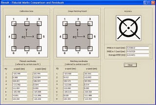
For the implementation, the cross correlation coefficient is employed to search for the fiducial marks. This can be said as a template matching problem. The application screens are shown below:


The program is developed using the C/C++ language using MS Visual Studio .NET 2003. I have not used any library. The image processing is done in pixel-wise using the class CImage that comes with MFC.

This program is part of my assignment for the Digital Photogrammetry subject (2010, Summer).

[Sourcecode][Executable][Assignment Report]

The source code is now available on Github: https://github.com/stanathong/fiducial_mark_detector.

LiDAR Viewer in 2D Raster Format

The LiDAR Viewer project is part of my assignment for LiDAR class (2009 Winter).

The application reads XYZ or XYZC file (in which X,Y,Z is 3D coordinates and C is color) and visualize the results in the form of 2.5D image. It offers zoom and pan functionality.

The program was developed using MS Visual Studio .NET 2003 using the CImage class for presenting image.

The application screen is presented below.


[Sourcecode][Executable][Testdata,7MB]

The source code is now available on Github: https://github.com/stanathong/lidar_viewer.

Object Oriented Change Detection of Rectangular Buildings after the Indian Ocean Tsunami Disaster

The tsunami of December 26, 2004 was one of the worst disasters in human history. Following a disaster, change detection is a prerequisite for quick assessments of damage. To assess the severity of devastation, most damage assessments focus on the destruction of man-made objects, particularly buildings.

In this work, we develop a robust rectangular building detection that can detect both small-size buildings in residential areas and large-size buildings in industrial areas. We use both edge detection and region growing approaches to supplement each other. The discovered buildings then become the inputs to our change detection. We employ knowledge based intelligent agents to recognize buildings before and after a disaster. The figure below presents the overview of the system implementation.

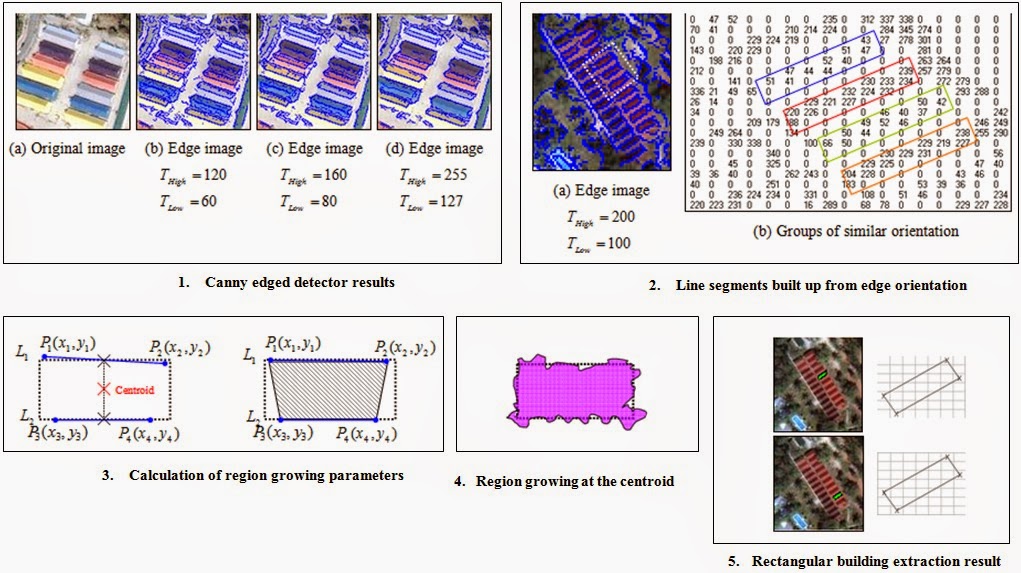
The figure below discusses the rectangular building extraction procedure which is a two-step process: 1) Edge detection by Canny detector, 2) Region growing.

The picture below presents the building candidates.

Specifying classification rules into the object-based change detection system, the detected changes are presented below:

Publications:
1. Tanathong, S., Rudahl, K.T., Goldin, S.E., 2009. Object oriented change detection of buildings after a disaster. Proceedings of ASPRS, Baltimore, USA. [PDF]
2. Tanathong, S., Rudahl, K.T., Goldin, S.E., 2008. Object oriented change detection of buildings after the Indian Ocean tsunami disaster. Proceedings of ECTI-CON, Krabi, Thailand. [PDF][LINK]
3. Tanathong, S., Rudahl, K.T., Goldin, S.E., 2007. Object-based change detection: the tsunami disaster case. Proceedings of ACRS, Kuala Lumpur, Malaysia. [PDF]